By: KP Soundararajan
This article focuses on the theoretical analysis of the radial-axial hobbing process, since there have not been many regular practices of this process. The industrial method is more towards axial hobbing, where the travel of the axial slide of the hobbing machine increases, and the target depth of the cut is implemented. On account of shortening the machining time, the axial process can take the chosen feed only in calculation, and the rest of the factors are part and hob related. Much of the hobbing analyses are based on these. Yet, there are workpieces where the part style and cluster arrangement may pose a challenge to direct axial hobbing and call for the radial axial method. This method, though known for several years, has no adequate research or well-drafted parametric relationships towards the chip formation and characteristics. So the effect on the tool wear behavior is relatively not well-documented.
For the application of radial infeed, the recommendation can be seen in literature. The shop floor practice is generally applied based on the machining circumstances, and there is no tool or methodology for efficiently using the radial / radial axial process. The ratio of radial feed to the radial path is equal to the ratio of corresponding axial infeed. This enables us to realize the process with constant machining time. Errors could creep in while applying this, due to reasons based on available mechanisms in the machine while chipping characteristics remain underutilized towards the hob wear.
The penetration calculation method based on the geometry of the gear/ process approach allows an automated determination of chip size and its geometry, taking into consideration the infeed angle. The influence of the infeed angle on cutting conditions is analyzed by a special program SpartAPRO theoretically, for different process designs, and calculates the cutting load on the hob for consideration.
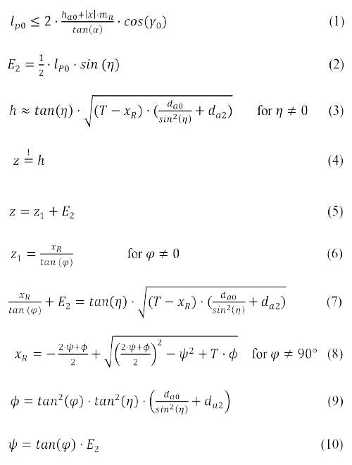
The following are the various process and geometric parameters which come into the determination of initial position of the hob and its axial slide.
The parameters and symbols used are as follows:
Hob diameter – dao
Enter distance – a
Hob axis position or center of hob – TCP
Radial displacement / offset position XR
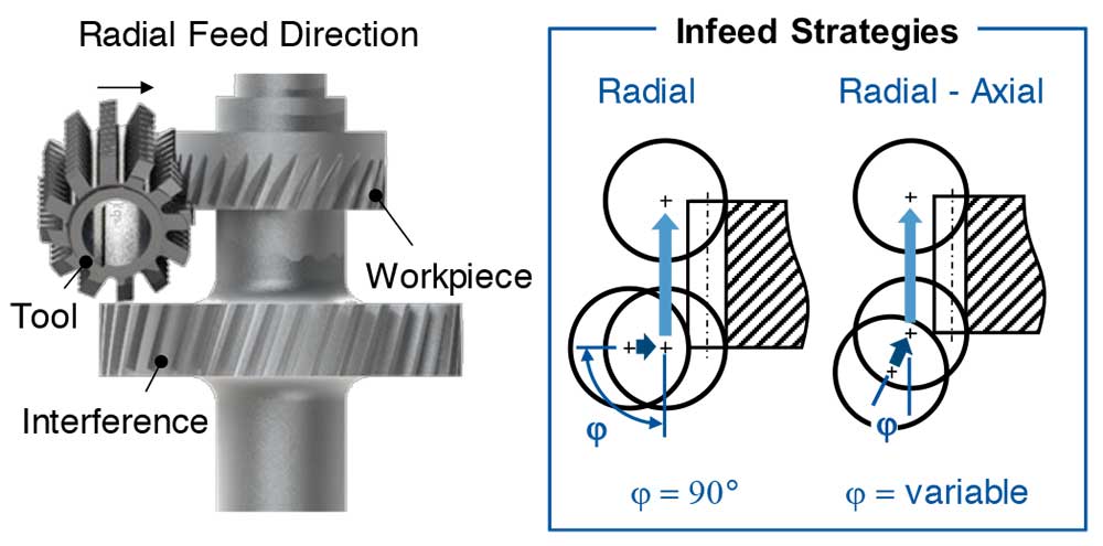
Fig.1: Infeed strategies for collision avoidance
Initial position of hob center corresponding to maximum level of highest point on penetration curve – Z&h
Approach path – E2
Infeed angle – (φ)
Hob head swivel angle – (η)
Profile forming length – lpo
Total/ whole depth of the tooth – T
Workpiece / Gear diameter – da2
Hob lead angle – γo
The starting position is the position at which the penetration curve coincides with the gear lower phase in the fixture. In addition to the end position, the axial and radial start locations should be determined for the given setup considering the hob diameter, target depth or infeed path to coincide the end of the radial path with the beginning of axial feed to complete the face width.
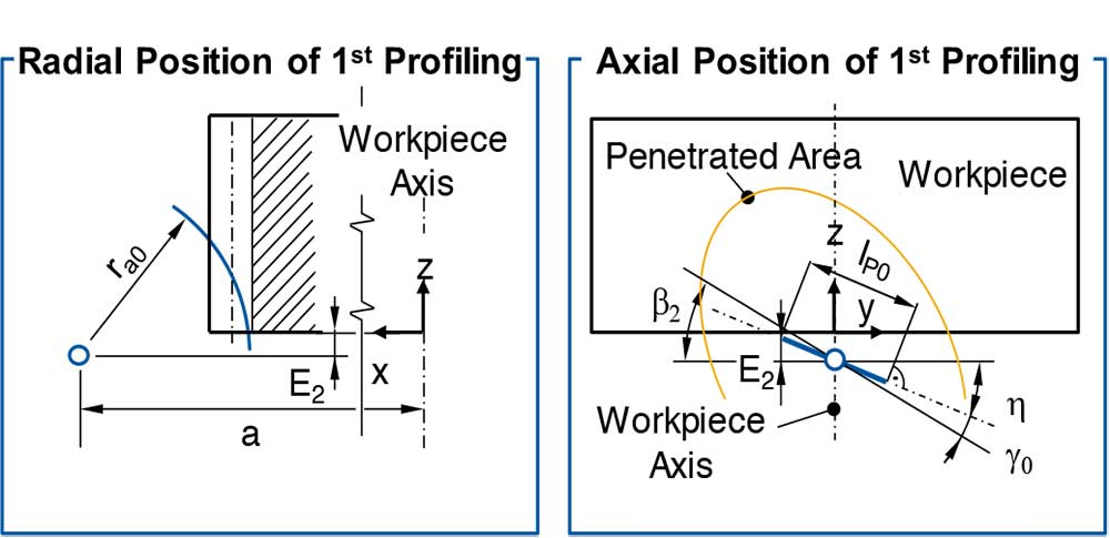
Fig 3: Determination of the position of first profiling
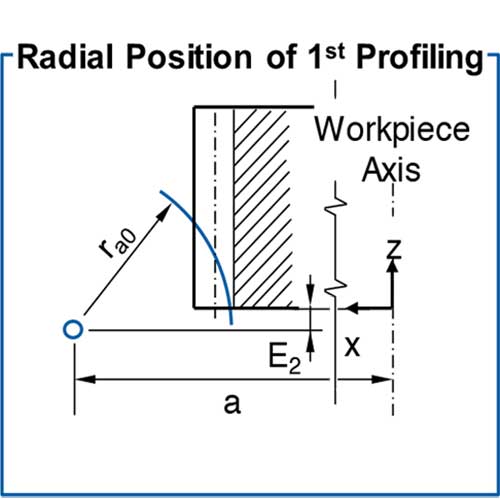
Fig 4: Determination of the starting position
Process description on influence of infeed angle on chipping characteristics:
A) Constant path feed rate
a) As infeed angle increases, number of cuts decrease and required infeed distance decreases.
b) Hob has to travel a short distance, and the number of workpiece revolutions is relatively less. The hob reaches the target position in radial direction in a shorter time.
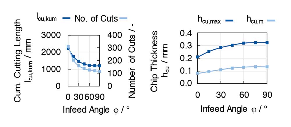
Fig 5: Chipping characteristics at constant path feed rate
B) Behaviors:
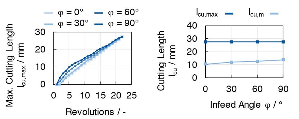
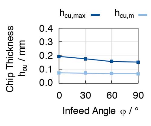
Fig 6: Characteristics at constant machining time
a) Under constant machining time, the cumulative cutting length and required number of cuts increase with increasing infeed angle.
b) Mean chip thickness and maximum chip thickness decrease with higher infeed angle
c) The above reduces the load on the hob, but the number of cuts increase along with mean and cumulative cutting length.
The process analysis with the developed tool provides several opportunities to explore further in the radial axial hobbing of helical gears. It opens up new trends not covered by the process know-how so far studied in axial hobbing alone by the Hoffmeister Method.
These open up many more trial opportunities to understand the analytical behavior or the process for knowledgeable application and use.
References:
1 ScienceDirect/ procedia CIRP 79/2019/68-73
2 Fette for precision / pages 128-130
 The author is former Director and General Manager of Gleason Works India. He has four decades of experience in the gear industry, with special reference to machine tools and gear processes. He is also a Fellow of the Institution of Mechanical Engineers, UK, and a registered chartered engineer.

We are India’s first and only multifaceted Web Platform catering to Indian Gear Manufacturers & Gear related Industries.
![]()