Gear wheels have been used for transmitting motion since the 3rd century BC (Ref. 1). Yet, the evolution of this transmission technology continues to date and finds its inevitable need in numerous applications. The multifaceted advancements in design, material, tribology and other areas collectively help the improvement of transmission efficiency, noise vibrational performance, durability and effective manufacturability of the gears (Ref. 2). Today, gearboxes are inevitable in numerous applications requiring high power density including wind turbines, electric vehicles, cranes, robotics, etc. A combination of high-ratio gearboxes with high-speed, low-torque motors is often used to achieve high power density (Ref. 3). Planetary gear trains (PGTs) help achieve a high gear ratio in a compact arrangement. Several configurations of planetary gears are widely studied in Refs. 4–8 where the gear profiles used in these studies are primarily involute.
From simple geometries like straight profiles to cycloids and then to the involutes, the evolution of gear profile geometry has been centuries (Refs. 9 and 10). The concept of profile shifting and the CNC manufacturing process that began in the late 1970s marked an important revolution in transmission systems and helped the manufacturing of precise and mass quantities of standardized gears. To this day, involute gears have found their use in every possible application despite their continuous betterment. The strongly established standards and guidelines like AGMA have provoked the large commercialization of involute gears. Numerous computation and design software including KISSsoft, ROMAX, Simcenter, MESYS, etc. help in involute gear design and analysis. This software not only helps to design simple gear trains but also enables us to optimize the design based on the contact/ meshing performance, and manufacturability. Although the advantages of involute gears like easy manufacturability, and insensitivity to center distance deviations are critical for its choice, the well-established standards in the previous decades and mass commercialization compels the use of involute gears. Because of this, the developments on other gear profiles (non-involutes) are very limited to this date despite the enormous advancement in high-precision manufacturing technologies (Ref. 11).
The downsides in involute gears like high-sliding velocities at the meshing extremes and low surface-load capability can be overcome with other gear geometries like cycloids and circular arcs (Ref. 12). Typically, the modifications are classified based on gear profile, flank and lead parameters (Ref. 13). The research works of Parsons (Ref. 14) show lead and flank modification of gears that help increase the load-carrying capacity of gears and better noise characteristics while Shen et. al. (Ref. 15) and Berlinger (Ref. 16) employ profile modification for achieving high efficiency and load-carrying capacity respectively. Yet, increased transmission error and sensitivity to manufacturing inaccuracies deter the usage of these unconventional gear profiles.
Through this paper, a review of unconventional gear profiles in planetary gear is presented and how future research in this direction benefits several applications. The analyses of different gear profiles show that some unconventional gear profiles have better meshing efficiency and load-bearing capacity than the involute gears. However, they are heavily constrained by their high transmission error and manufacturing inaccuracies.
“Overview of planetary gear trains and increasing the overall efficiency” provides an overview of planetary gear trains (PGTs) to understand the importance of high meshing efficiency in extreme gear ratios. In “Critical parameters to evaluate different gear profiles,” a short description of the evaluation criteria of different gear profiles is briefed. “Unconventional gears in PGT” reviews planetary gearboxes with non-involute gear profiles from the literature and the potential gear profiles that can help to improve the efficiency of the high-ratio gearbox. Finally, a discussion on the confrontation of different gear profiles based on the evaluation criteria is provided in “Discussion” which is followed by conclusions and recommendations in “Conclusions.”
Planetary gears are compactly arranged gear trains that achieve high gear ratios with good efficiency. Traditionally, large gear ratios are achieved by coupling several planetary gear stages together which is known as a stacked arrangement—refer to Figure 1 (left). The efficiency of multistage PGTs (or stacked PGTs) is high (above 90%) even at gear ratios around 100:1 (Refs. 17, 18). However, the involvement of several stages is a severe downside of these gearboxes thereby becoming a bulky, heavy, and costlier solution.
On the other hand, an extremely compact arrangement of planetary gear trains known as the Wolfrom configuration (also called coupled-PGT, differential-PGT or 3K-PGT) is an extremely power-dense transmission system that however comes at the cost of very low efficiency, refer to Figure 1, (Refs, 4, 5, 8, 19, 20).
This type of gearbox has the potential to bring a massive transformation in several applications due to its high-torque-density nature. Yet at this juncture, they are restricted to extremely poor efficiency at high reduction ratios due to latent power inherent to this configuration (Refs. 21, 22).
Wolfrom gearbox efficiency is characterized by the gear ratio and the meshing efficiency of involved gear pairs. From (Ref. 4), the Wolfrom gearbox efficiency is given as:
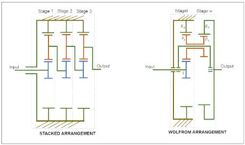
Fig 1: Planetary gear train configurations: (Left) stacked arrangement, (Right) Wolfrom-PGT
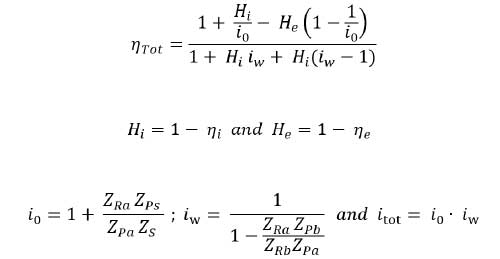
where
ηTot is the total efficiency of the gearbox
i0, iw, itot are the gear ratios in stage-0, stage-w and total gearbox respectively
Hi, He are the gear loss factors in internal and external gear meshing respectively
ηi, ηe are the meshing efficiencies in internal and external gear meshing respectively
Z is the number of teeth in the respective gear wheels
This shows that in a Wolfrom planetary gear train (differential), the meshing efficiency of gears is extremely crucial as the gear ratio increases. Figure 2 is a representative example of a Wolfrom-PGT where the evolution of a gearbox efficiency is plotted in function of gearbox ratios for different meshing efficiencies (Ref. 23). For high gear ratios (e.g., 300:1), even a small increase of 0.5% in meshing efficiency will decrease the gearbox loss by more than one third of the initial loss.
High gearbox efficiency is of paramount importance not only to reduce energy losses but also to have better backdrivability. Backdriving is the principle of switching the natural input and output of the gearbox (Ref. 21). Hence the power flow from the input (motor) to the output (load) is reversed where a reducer gearbox becomes then a multiplier. This is one of the key characteristics deemed in several modern applications including collaborative robotics (Ref. 24). The gearbox in general is backdrivable when the overall efficiency is more than 50% in normal operation—forward driving—(Refs.25, 26).
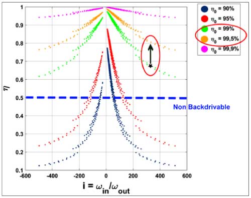
Fig 2: Evolution of gearbox efficiency for a three-stage PGT in the function of gear ratio for different meshing efficiency from (Ref. 23)
The gear performance can be characterized based on several phenomena even if it is involute or non-involute gear. Namely the load-carrying capacity, meshing efficiency, manufacturability, vibrational behavior and lifetime, etc. The primary criteria to evaluate the different gear profile geometry are discussed further.
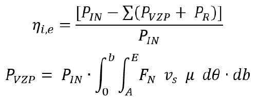
The power loss in gears is associated with both loaded and no-load conditions as described in (Ref. 27). The meshing losses can be calculated from:
where
η_(i,e) is the meshing efficiency of gears
P_IN is the input power (kW)
P_VZP is the load-dependent power loss integrated along the path of action-AE and facewidth-b (kW)
P_R is the summation of all other losses due to gear no-load, bearings, lubrication, seals, etc. (kW)
μ is the coefficient of friction
F_N is the normal force acting on the gear tooth (N)
v_s is the sliding velocity of the gears in mesh (m/s)
dθ,db are the integrating segments along the line of action (rotation) and the facewidth of the gears
Gear wheels in action are characterized by the load transmitted and to what extent of efficiency. This is mainly dependent on the bending stress at the root and the contact stress at the surface of the teeth which influences their performance and lifetime. Considering the real operation, several factors depending on uniform/varying loads, lubrication conditions, and accuracy of manufacturing are derived from the standards and incorporated into the stress formulae.
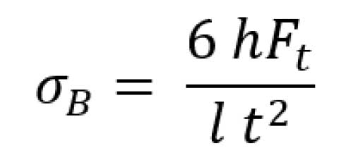
The gear tooth fillet or the root stress is responsible for the breakage or tooth rip-off failure in gears. It is calculated assuming the cantilever beam principle and given by Equation 6. AGMA standards use additional factors considering manufacturing deviations, uniformity of load, distribution pattern in the helical system, fatigue profiles etc. (Ref. 28).
where
h is the height of the load point from the tooth root (mm)
Ft is the tangential force of the tooth (N)
l is the facewidth (for spur gears) or effective length along facewidth (for helical gears) (mm)
t is the thickness of the tooth at pitch circle (mm)
The contact stress in gears is responsible for the surface failure of the gear tooth. This failure leads to the pitting and scoring on the gear tooth affecting the lifecycles of the gears. The fatigue property of the material is critical to this stress. As a general approximation in involute gears, the contact stress is given by the Hertz formula (Ref. 28):
where
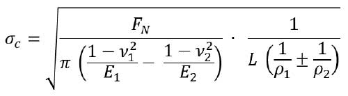
FN is the normal force (N)
ν1,ν2 are the Poisson ratios
E1,E2 are the Young’s modulus
L is the facewidth (for spur gears) or minimum length of contact (for helical gears) (mm)
ρ1,ρ2 are the effective normal radii of curvatures of gears with + for external & – for internal gears
The contact stress is calculated along the tooth surface at each point of contact. In general, the maximum load point corresponds to the single tooth of action where the entire load is concentrated to one pair of gear teeth.
For a given gear ratio, the deviation in the rotation of the gear for an equivalent rotation of pinion is called the transmission error. Transmission error is responsible for the noise and vibration of gears. The transmission error is an effect of both the gear design aspect and manufacturing inaccuracies of gears.
The design aspect comprises tooth deflections based on the load and the profile/lead modifications done to the gear profile for uniform wear patterns, etc. (Ref. 29).
The change in relative stiffness between gear teeth is kept to a minimum level for low vibration and noise conditions in gears which is handled by maximizing the gear contact ratio (Ref. 30). However, as the contact ratio increases along the transverse plane, the meshing extremes are far from the pitch point and thus the sliding velocities are high which is a trade-off in terms of meshing efficiency. On the other hand, it can be seen as an effective length of deformation during the meshing cycle; the more the gear teeth deform during meshing, the larger the area of the wear and thus the larger the friction and the power losses are. This can also be understood with the expressions given in “Meshing efficiency” where the necessity for keeping the sliding velocity low to reduce the power loss is evident.
In recent years, non-involute gears have started finding their place in high ratio gearboxes to increase the efficiency and load-carrying capacity of gearboxes. The advancements in rapid prototyping and precision manufacturing methods further enable fabricating complex geometries in a relatively efficient manner that supports testing and advanced analyses of gears. In the following section, some planetary gear trains that exclusively
use unconventional gears are reviewed and their characteristics are discussed.
Low-loss gears described in Ref. 31 are optimized gears for high meshing efficiency. Although the fundamental tooth shape is involute, the low-loss gears involve unconventional profile modifications to a large extent as shown in Figure 3. The tooth has reduced addendum, large pressure angle, small module and large helix angle and facewidth which contributes to decreasing the transverse contact ratio in gears. Although the increase of the helix angle, in principle, leads to a larger power loss (Ref. 31), the effect is countered by the increase in pressure angle and reduction of the gear modulus. Since the transverse contact ratio (εα) is kept to a minimal value, the meshing region involves a shorter approach and recess lengths leading to lower sliding velocities. To maximize the load-carrying capacity, the total contact ratio (εα+ εβ) is maintained by increasing the overlap ratio (εβ) of helical gears.
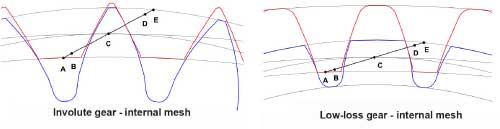
Fig 3: Internal meshing of low-loss gears (Ref. 6)
Since low-loss gears have high meshing efficiency, this helps when used in a Wolfrom configuration to reach high gear ratios in a compact way and yet with good efficiency. Ref. 6 describes three different configurations of PGTs in which low-loss gears were tested initially. The results from Ref. 32 also prove that the weight of the Wolfrom gearbox is nearly reduced by 50% compared to the conventional planetary gear train of the same gear ratios although the overall efficiency deteriorates due to the configuration itself. Such a gearbox will be highly beneficial in high torque applications like wind turbines and automotive gearboxes if the efficiency could be further improved (Ref. 33).
As the involutes are the base geometry of the gear tooth profile, the manufacturability is said to be standard. Compared to the standard involute gears, the low loss gears exhibit large meshing stiffness and are more prone to manufacturing inaccuracies (Ref. 34). With the reduction in transverse contact ratio, the contact happens thus in a small domain consequently increasing the noise generated.
The convex-concave gears discussed in Ref. 35 share the basics of cycloidal gear teeth where the curve of action is an S-shape curve defined by two individual radii corresponding to the pinion and gear as shown in Figure 4.
The shape of the corresponding gear tooth following this curve of action is derived from differential geometry and gearing law (Ref. 36). The meshing efficiency of convex-concave reaches similar levels to that of involute gears for an ideal profile curvature. However, the loading condition significantly varies during the approach and recess cycle in the meshing.
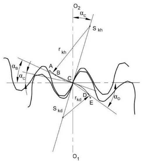
Fig 4: Meshing of convex-concave profile gears from (Ref. 35)
Compared to involutes, the convex-concave gears are gradually loaded and the peak load is taken by the tooth at the pitch point where the pressure angle is the least. Away from the pitch point, the pressure angle increases and therefore the load on the tooth is also lesser. The high sliding velocities at the start and end of meshing present in involute gears are eliminated with the convex-concave gears also due to the curved meshing action.
Brumercik et al. presented a reduced planetary gearbox with a convex-concave gear tooth profile (Ref. 37). The authors developed a small prototype to test this gear profile for a gear ratio of above 70:1 where Nylon 6.6 (PA66) gears were used. The results showed a favorable relative sliding between gears compared to the involute profile. Although the rapid prototyping method used is subject to manufacturing inaccuracies, such a small and lightweight gearbox could be used in applications such as a car’s rear-view mirror.
Double-circular arc gears were initially proposed by Litvin (Refs. 38, 39) which was derived based on the Wildhaber and Novikov circular arc gears (Refs. 40, 41). The double-circular arc gear proposed by Litvin is characterized by three circular arcs: one on the crown part, one on the base part and the other connecting the formers as shown in Figure 5. Later, Wang (Ref. 42) adapted this profile to overcome the discontinuity in profile curves and proposed a new type of double-circular arc gears as shown in Figure 5.
Due to the concavity and convexity nature of meshing and the resulting lower surface stress, this type of profile can handle much more torques and spans longer life compared to similar-size involute gears. Further, there is no limitation in the number of teeth, unlike involute gears. This type of gear is extremely sensitive to manufacturing inaccuracies and center distance deviations that reduce efficiency.
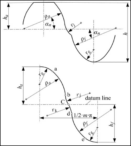
Fig 5: Double-circular arc gears proposed by Litvin (top) and Wang (bottom). Image adapted from (Ref. 52)
Wang analyzed the influence of these profiles by using them in a conventional planetary gear train (Ref. 42). The three-stage stacked planetary arrangement studied by the author had a gear ratio of 103:1 with the first two stages of 5.143:1 and the last stage 3.9:1 gear ratio respectively. Due to its lower efficiency and high load capacity, this kind of gearbox finds its better suitability in winch applications (Ref. 42).
Several other gear profiles exist apart from the ones mentioned above. A review of non-involute gear profiles by Okorn (Ref. 43) summarizes the design and capability of each profile. The unique profiles for which the meshing efficiency is deemed to be better than involute gears and can be of interest in using in Wolfrom gearboxes are discussed below:
The S-gears developed by Hlebanja (Ref. 44) are generated by a specific rack design. The rack generates a specific concave-convex gear profile for which the meshing curve is in the shape of “S” as shown in Figure 6.
S-gears show a good load-carrying capacity because of their broader tooth root and concave-convex meshing compared to involutes. Additionally, since the relative sliding velocities are reduced during the start and end of meshing, the power loss due to friction is lower. These gears initially used in rolling mills are now finding their use in several applications. The S-gears-based high ratio gear drives described in Ref. 45 are used mainly in marine, aircraft and robotic applications.
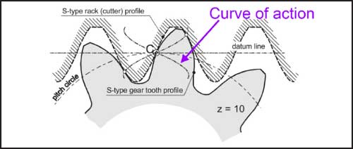
Fig 6: Rack cutting S-gears adapted from (Ref. 56)
Pure rolling helical gears described by Chen et al. (Ref. 46) are based on a circular arc gear tooth geometry. The circle inscribed for the tooth geometry has the center in the tangent connecting the base cylinders of the gears in the mesh as shown in Figure 7. The radius of this circle is shorter than the length from the tangent point on the base circle to the pitch point. In other words, the radius of curvature about the pitch point is shorter compared to the equivalent involute gears. Additionally, these gears use the Hermite function to obtain the root fillet radius.
A convex-convex meshing happens and as a result, the load transmission is restricted to a very small region increasing the contact stress and promoting more rolling action in gears. The local deformations in the gear tooth still exist and minimal sliding is expected to happen. The application of this gear profile to internal gears and high-ratio gear drives has not been analyzed yet. Additionally, their experimental performances are also not known yet.
Cycloidal and involute gears have their own individual advantages and disadvantages. But the advantages of these two gears were combined in the involute-cycloid composite gears discussed in Ref. 47. As shown in Figure 8, the profile geometry is composed of epicycloid and hypocycloid for the addendum and dedendum extremes respectively and a portion of involute only around the pitch diameter region.
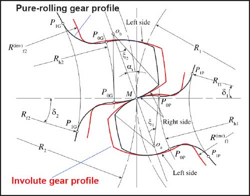
Fig 7: Pure rolling gear profiles in mesh adapted from (Ref. 46)
Because of the involute profile around the pitch diameter, the action curve is linear to a limited extent about the pitch point of the meshing curve and making this gear less sensitive to the center distance deviations. The cycloid tooth profile increases the surface-load capacity and reduces the sliding velocities considerably at the meshing extremes. Therefore, the involute-cycloid composite gears have better meshing efficiency. Due to the involvement of cycloid for the dedendum part, undercutting is avoided, and small numbers of teeth could be realized. While the contact stress values are better compared to involutes because of the convex-concave contact, the root bending stress values see a significant increase due to reduced root thickness [48].
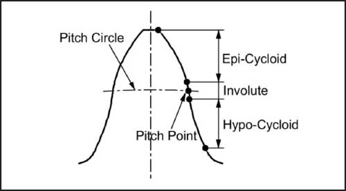
Fig 8: Involute-cycloid composite gear profile (Ref. 47)
A comparison of high ratio planetary gear trains having different tooth profile geometries is provided in Table 1. Amongst the candidates, two variants of Planetary gear trains that were discussed initially are identified: namely the Stacked and Wolfrom arrangement. For the involute-profile PGTs, characteristic examples of commercial gear heads and novel gearboxes from the literature are also compiled. The transmission ratio of around 100:1 is observed for all the examples except one for which the gear ratio is 70:1.
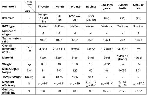
* estimated, n/a: information not available Table 1: Comparison of Planetary gear trains with non-involute profiles
Table 2 gives a comparison of unconventional gear profiles discussed in the previous section and their performance levels. The analysis shows that although low-loss gears have very good efficiency, they suffer from increased bending and contact stresses and transmission error due to a limited contact ratio, which is a strong disadvantage. The cycloid gears, involute-cycloid composite and the double circular arc gears have nearly similar performance capabilities because of their similarity in convex-concave contact between meshing gears. However, their sensitivity to center distance deviations and manufacturing errors poses limitations. Pure rolling gears and the S-gears, on the other hand, perform better in terms of efficiency and bending stress but the surface stress limits of pure-rolling gears are critically lower due to the convex-convex contact nature. Both S-gears and pure rolling gears are subject to high transmission error because of the reduced contact ratios. Even though the sensitivity to center distance deviation is influential to a limited extent in S-gears because of the local line of action (instead of a curve), S-gears are prone to manufacturing inaccuracies. The non-involute gear profiles in general, can improve meshing efficiency and load-carrying capacity of gears compared to the standard involute gears. If their transmission error and manufacturability aspects are improved compared to standard involute, their usage in high ratio PGTs could be beneficial.
The overall efficiency of high-ratio planetary gear trains with involute gears drops severely at reduction ratios of several hundred. Other unconventional gears could help solve this problem by achieving better meshing efficiencies than involute gears. A review of planetary gear with unconventional gears is presented in this paper. Several research groups already work individually on different non-involute gear profiles and the analyses show that the Wolfrom-gearbox—a compact type of planetary gear to achieve high ratios—is predominantly used to test the changes in gear profiles compared to the conventional stacked PGTs type.
A set of evaluation criteria that are fundamental to assessing gear profiles are briefed after which the design, performance and use of a few non-involute gear profiles are then discussed. The non-involute gear profiles like S-gears and pure rolling helical gears play a significant role in improving the meshing efficiency of the gears, while the convex-concave gears (cycloid) handle the contact loads in a better way. However, the real-time performance and absolute degree of improvement are little known yet due to the unavailability of all evidence in the literature. So, a relative comparison is done, and the profiles are confronted.
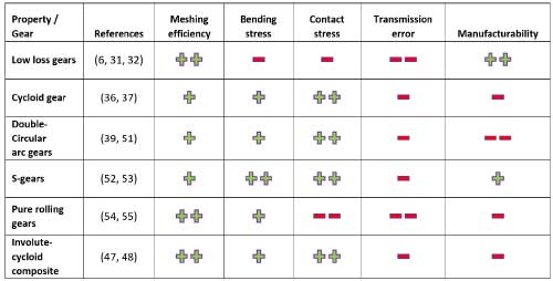
Table 2: Comparison of unconventional gear profiles that are used in the Planetary gearbox or favorable to use to have better efficiency. Based on the referred articles and simulations, the candidates are rated from poor (– –) to best (++).
The non-involute gear profiles can improve meshing efficiency and load-carrying capacity of gears compared to the standard involute gears. But the reduced contact ratio and nonstandard manufacturing techniques have a negative influence on their accuracy, noise and vibration characteristics making them less preferred. Moreover, the dominance of involute gears which are backed by well-established standards undermines the potential of other gear profiles. Leveraging the advancements in present-day manufacturing technology, future research will be focused on improving the key characteristics of gears with high meshing efficiency so that when used in a high-ratio gearbox like Wolfrom, the power loss could be reduced drastically.
References
1. M. J. . Lewis, “Gearing in the ancient world,” Endeavour, vol. 17, no. 3, pp. 110–115, Jan. 1993, doi: 10.1016/0160-9327(93)90099-O.
2. S. P. Radzevich, Recent Advances in Gearing. Cham: Springer International Publishing, 2022. doi: 10.1007/978-3-030-64638-7.
3. S. Crispel et al., “A novel wolfrom-based gearbox for robotic actuators,” IEEE/ASME Transactions on Mechatronics, vol. 26, no. 4, pp. 1980–1988, 2021, doi: 10.1109/TMECH.2021.3079471.
4. H. W. Müller, Epicyclic Drive Trains. Detroit: WAYNE STATE UNIVERSITY PRESS, 1982.
5. K. Arnaudov and D. P. Karaivanov, Planetary Gear Trains, 1st ed. Boca Raton: CRC Press, 2019. doi: 10.1201/9780429458521.
6. B.-R. Höhn, K. Stahl, and P. Gwinner, “Improved Efficiency for High-Ratio Planetary Gear Transmissions: Low-loss Wolfrom transmission for wind turbines,” International Conference on Gears, pp. 1113–1124, 2013.
7. J. Liang, D. Qin, W. Wen, and J. Jiang, “Research on Efficiency and Load Sharing Characteristics of High-Speed-Ratio Planetary Gear Transmissions,” in Volume 10: ASME 2015 Power Transmission and Gearing Conference; 23rd Reliability, Stress Analysis, and Failure Prevention Conference, Aug. 2015, pp. 1–10. doi: 10.1115/DETC2015-46245.
8. A. Kapelevich, “High gear ratio epicyclic drives analysis,” American Gear Manufacturers Association Fall Technical Meeting 2013, June, pp. 61–72, 2013.
9. E. E. Osakue and L. Anetor, “A method for constructing standard involute gear tooth profile,” ASME International Mechanical Engineering Congress and Exposition, Proceedings (IMECE), vol. 13, pp. 1–11, 2018, doi: 10.1115/IMECE2018-86573.
10. J. S. S. Edwards, “Gearing,” in The New Palgrave Dictionary of Economics, December, Basingstoke: Nature Publishing Group, 1985, p. 1. doi: 10.1057/9780230226203.2624.
11. H. Stadtfeld and J. Saewe, “Non-Involute Gearing, Function and Manufacturing Compared to Established Gear Designs,” Gear Technology, February, pp. 42–51, 2015.
12. Y. Peng, A. Song, Y. Shen, and X. Lin, “A novel arc-tooth-trace cycloid cylindrical gear,” Mechanism and Machine Theory, vol. 118, pp. 180–193, 2017, doi: 10.1016/j.mechmachtheory.2017.08.009.
13. A. E. Mehr and S. Yoders, “Efficient hard finishing of asymmetric tooth profiles and topological modifications by generating grinding,” AGMA 2016—Fall Technical Meeting, August, pp. 76–83, 2016.
14. B. N. V. Parsons, D. Walton, L. Andrei, and G. Andrei, “Non-standard cylindrical gears,” Gear Technology, November, vol. 21, pp. 30–37, 2004.
15. W. Sheng, Z. Li, H. Zhang, and R. Zhu, “Geometry and design of spur gear drive associated with low sliding ratio,” Advances in Mechanical Engineering, vol. 13, no. 4, pp. 1–12, 2021, doi: 10.1177/16878140211012547.
16. B. E. Berlinger and J. R. Colbourne, “Convoloid Gearing Technology,” Gear Technology, no. 2, pp. 50–57, 2012.
17. “WITTENSTEIN – Technische Broschüre SP+ und TP+ Getrieben. Katalog.” Technische Broschüre SP+ und TP+ Getrieben. Katalog
18. “Neugart -Planetary Gearboxes – PLE Series.” https://www.neugart.com/en/products/planetary-gearboxes-with-output-shaft/ple
19. K. Arnaudov and D. Karaivanov, “The Wolfrom Gear Train: A Case of Highest-Complexity Related Modifications of the Tooth Meshing,” in International Design Engineering Technical Conferences & Computers and Information in Engineering Conference, Jan. 2009, pp. 89–94. doi: 10.1115/DETC2009-86793.
20. S. Crispel et al., “Introducing Compound Planetary Gears (C-PGTs): A Compact Way to Achieve High Gear Ratios for Wearable Robots,” in Biosystems and Biorobotics, October, vol. 22, 2019, pp. 485–489. doi: 10.1007/978-3-030-01887-0_94.
21. P. L. García, S. Crispel, E. Saerens, T. Verstraten, and D. Lefeber, “Compact Gearboxes for Modern Robotics: A Review,” Frontiers in Robotics and AI, August, vol. 7, pp. 1–8, Aug. 2020, doi: 10.3389/frobt.2020.00103.
22. C. Chen and J. Angeles, “Virtual-power flow and mechanical gear-mesh power losses of epicyclic gear trains,” Journal of Mechanical Design, Transactions of the ASME, vol. 129, no. 1, pp. 107–113, 2007, doi: 10.1115/1.2359473.
23. S. Crispel and E. Saerens, “Master Thesis : Study and development of a high torque , high efficient infinite variable transmission ( IVT ) for assistive exoskeleton actuation,” Vrije Universiteit Brussel, 2017.
24. A. Wang and S. Kim, “Directional efficiency in geared transmissions: Characterization of backdrivability towards improved proprioceptive control,” in 2015 IEEE International Conference on Robotics and Automation (ICRA), May 2015, vol. 2015-June, pp. 1055–1062. doi: 10.1109/ICRA.2015.7139307.
25. H. Matsuki, K. Nagano, and Y. Fujimoto, “Bilateral Drive Gear – A Highly Backdrivable Reduction Gearbox for Robotic Actuators,” IEEE/ASME Transactions on Mechatronics, vol. 24, no. 6, pp. 2661–2673, 2019, doi: 10.1109/TMECH.2019.2946403.
26. P. L. Garcia et al., “R2poweR: The Proof-of-Concept of a Backdrivable, High-Ratio Gearbox for Human-Robot Collaboration,” in 2022 International Conference on Robotics and Automation (ICRA), May 2022, pp. 01–07. doi: 10.1109/ICRA46639.2022.9811923.
27. C. M. C. G. Fernandes, P. M. T. Marques, R. C. Martins, and J. H. O. Seabra, “Gearbox power loss. Part II: Friction losses in gears,” Tribology International, vol. 88, pp. 309–316, 2015, doi: 10.1016/j.triboint.2014.12.004.
28. AGMA 908-B89, “Geometry Factors for Determining the Pitting Resistance and Bending Strength of Spur, Helical and Herringbone Gear Teeth.” American Gear Manufacturers Association, Alexandria, 1989.
29. M. Åkerblom, “Gear noise and vibration: a literature survey,” Trita-MMK NV—2001:11, p. 25, 2001.
30. U. Kissling and M. Raabe, “Calculating Tooth Form Transmission Error,” in Gear Solutions, vol. 1, Sep, Pelham, AL, 2006, pp. 38–66.
31. B. R. Höhn, K. Michaelis, and A. Wimmer, “Low Loss Gears—05FTM11—AGMA,” AGMA Paper – AGMA-Fall Technical Meeting Detroit, Michigan/USA, October 16-18 (2005), Paper 05FTM11. pp. 1–11, 2005.
32. B. Höhn, K. Stahl, and P. Gwinner, “Light-Weight Design for Planetary Gear Transmissions,” Gear Technology, September, pp. 96–103, Sep. 2013.
33. M. Hinterstoißer, B. R. Höhn, and K. Michaelis, “Optimization of Gearbox Efficiency,” Goriva i maziva, vol. 48, no. 4, pp. 462–480, 2009.
34. K. Michaelis, B. R. Höhn, and M. Hinterstoißer, “Influence factors on gearbox power loss,” Industrial Lubrication and Tribology, vol. 63, no. 1, pp. 46–55, 2011, doi: 10.1108/00368791111101830.
35. F. Brumercik, M. Lukac, M. Majchrak, Z. Krzysiak, and L. Krzywonos, “Teeth geometry and contact pressure calculation of external cycloidal gears,” Scientific Journal of Silesian University of Technology Series Transport, vol. 101, Dec, pp. 27–35, Dec. 2018, doi: 10.20858/sjsutst.2018.101.3.
36. M. Bodanský, M. Vereš, and J. Gaduš, Theory of Convex-Concave and Plane Cylindrical Gearing. Bratislava: Slovak University of Technology, 2006.
37. F. Brumercik, M. Lukac, J. Caban, Z. Krzysiak, and A. Glowacz, “Comparison of selected parameters of a planetary gearbox with involute and convex-concave teeth flank profiles,” Applied Sciences (Switzerland), vol. 10, no. 4, pp. 1–16, 2020, doi: 10.3390/app10041417.
38. F. L. Litvin and J. Lu, “New Methods for Improved Double Circular-Arc Helical Gears,” Contractor, July, 1997.
39. F. L. Litvin, P.-H. Feng, and S. A. Lagutin, Computerized Generation and Simulation of Meshing and Contact of New Type of Novikov-Wildhaber Helical Gears. NASA, 2000.
40. E. Wildhaber, “Helical gearing,” United States Patent Office, US1601750, 1923.
41. M. L. Novikov, “USSR Patent: 109,750,1956.”
42. C. Y. Wang, “Design of planetary gear reducer with double circular-arc helical gear,” Applied Mechanics and Materials, vol. 152–154, pp. 1595–1600, 2012, doi: 10.4028/www.scientific.net/AMM.152-154.1595.
43. I. Okorn, M. Nagode, and J. Klemenc, “Operating performance of external non-involute spur and helical gears: A review,” Strojniski Vestnik/Journal of Mechanical Engineering, vol. 67, no. 5, pp. 256–271, 2021, doi: 10.5545/sv-jme.2020.7094.
44. J. Hlebanja, G. Hlebanja, and M. Umberger, “S-Gear Design Rules,” 2020.
45. G. Hlebanja and S. Kulovec, “Development of a Planocentric Gear Box Based on S-Gear Geometry,” Kolloquium Getriebetechnik, pp. 205–216, 2015, doi: 10.14459/2015md1276145.
46. Z. Chen, M. Zeng, and A. Fuentes-Aznar, “Geometric design, meshing simulation, and stress analysis of pure rolling cylindrical helical gear drives,” Proceedings of the Institution of Mechanical Engineers, Part C: Journal of Mechanical Engineering Science, vol. 234, no. 15, pp. 3102–3115, 2020, doi: 10.1177/0954406220912265.
47. K. Ikejo, K. Nagamura, and F. G. Tutulan, “Friction Loss of Non-Involute Tooth Profile Gears,” in Volume 5b: Power Transmission and Gearing Conference, 2005, vol. 2005, pp. 657–663. doi: 10.1115/DETC2005-84148.
48. F. G. Tutulan, K. Nagamura, and K. Ikejo, “Tooth Root Stress and Tooth Contact Stress of the Modified Cycloid Helical Gear,” in Volume 4: 9th International Power Transmission and Gearing Conference, Parts A and B, Jan. 2003, vol. 4 A, pp. 91–96. doi: 10.1115/DETC2003/PTG-48012.
49. J. Looman, Zahnradgetriebe. Berlin, Heidelberg: Springer Berlin Heidelberg, 1996. doi: 10.1007/978-3-540-89460-5.
50. Y. Fujimoto, “Bilateral Drive Gear : a Highly Backdrivable Reduction Gearbox for Robotics,” 2021. https://www.youtube.com/watch?v=3zbuwhy-OPo
51. H. Zhang, L. Hua, and X. Han, “Computerized design and simulation of meshing of modified double circular-arc helical gears by tooth end relief with helix,” Mechanism and Machine Theory, vol. 45, no. 1, pp. 46–64, 2010, doi: 10.1016/j.mechmachtheory.2009.08.001.
52. I. Okorn, M. Nagode, and J. Klemenc, “Operating performance of external non-involute spur and helical gears: A review,” Strojniski Vestnik/Journal of Mechanical Engineering, vol. 67, no. 5, pp. 256–271, 2021, doi: 10.5545/sv-jme.2020.7094.
53. D. Zorko, J. Duhovnik, and J. Tavčar, “Tooth bending strength of gears with a progressive curved path of contact,” Journal of Computational Design and Engineering, vol. 8, no. 4, pp. 1037–1058, Jun. 2021, doi: 10.1093/jcde/qwab031.
54. Z. Chen, H. Ding, B. Li, L. Luo, L. Zhang, and J. Yang, “Geometry and parameter design of novel circular arc helical gears for parallel-axis transmission,” Advances in Mechanical Engineering, vol. 9, no. 2, pp. 1–11, 2017, doi: 10.1177/1687814017690957.
55. Z. Chen, M. Zeng, and A. Fuentes-Aznar, “Computerized design, simulation of meshing and stress analysis of pure rolling cylindrical helical gear drives with variable helix angle,” Mechanism and Machine Theory, vol. 153, p. 103962, Nov. 2020, doi: 10.1016/j.mechmachtheory.2020.103962.
56. G. Hlebanja, “Specially shaped spur gears: A step towards use in miniature mechatronic applications,” Balkan Journal of Mechanical Transmissions (BJMT), vol. 1, no. 2, pp. 25–31, 2011.
 Anand Varadharajan received a bachelor’s degree in mechanical engineering from Anna University, Chennai, India, in 2014, and a master’s degree in electromechanical engineering from Vrije Universiteit Brussel (VUB), Brussels, Belgium, and the Université libre de Bruxelles, Brussels in 2020.
 Dr. Pablo López obtained a master´s degree in industrial engineering with the Escuela Técnica Superior de Ingeniería Industrial de Gijón, Spain, in 1998. Since 2021, Pablo is an active member of the AGMA Committee on Robotics and
Automation.
 Stein Crispel received a bachelor’s degree in engineering from Vrije Universiteit Brussel (VUB), Brussels, Belgium, in 2015, and a master’s degree in electromechanical engineering from the Bruface Joint Master Program, VUB and the Université libre de Bruxelles, Brussels, in 2017.
 Prof. dr. ir. Bram Vanderborght obtained his doctorate from Vrije Universiteit Brussel (VUB) in 2007. Since 2009, he has been a professor at VUB. He is affiliated to the Interuniversity Microelectronics Institute (IMEC), Belgium, as scientific collaborator.
 Prof. dr. ir. Dirk is currently an emeritus Professor with the Department of Mechanical Engineering and the former head of Robotics and Multibody Mechanics Research Group, VUB.
 Prof. dr. ir. Tom Verstraten received a master’s degree in electromechanical engineering and a doctorate from Vrije Universiteit Brussel (VUB), in 2012 and 2018 respectively. In 2020, he became an assistant professor with the Robotics and Multibody Mechanics Research Group, VUB.

We are India’s first and only multifaceted Web Platform catering to Indian Gear Manufacturers & Gear related Industries.
![]()