– Snehal Raj
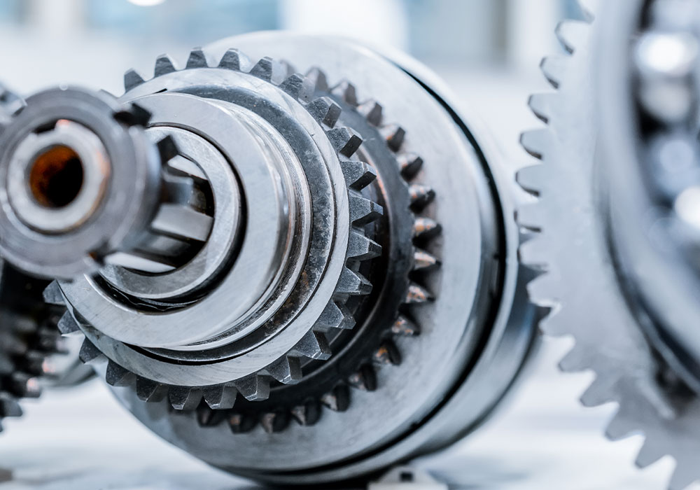
Gears are vital for machine functionality, transferring power and motion through their design. They regulate torque, speed, and direction with precision-crafted teeth. The design process involves achieving the right gear ratio, ensuring strength to withstand stress, and minimising backlash for accurate motion. Engineers optimise tooth profiles to reduce energy loss, wear, and noise, considering material selection, lubrication, and environmental factors for durability and performance.
Design challenges include balancing high torque with compact size and addressing dynamic factors like vibration and gear meshing forces. Manufacturing tolerances, surface treatments, and alignment affect performance, while maintenance features extend gear life and reduce costs. Embracing advancements in materials and manufacturing, engineers continually refine gear design for reliable and robust machinery performance.
An apparatus’ general health depends critically on its gear design. Vibration and frictional energy loss are reduced by well-designed gears, which run smoothly and accurately. This means that the machine will run more quietly, have fewer parts that wear out, and eventually last longer as a whole.
On the other hand, faulty design results in inefficiencies, noise, and early failure, all of which can be dangerous and expensive in terms of downtime. For maximum performance, gears need to be flawlessly designed. Even though CAD/CAM software enables engineers to precisely build complex gears, frequent design errors can still occur, leading to inefficiencies and sometimes equipment breakdowns.
Understanding gear fundamentals is crucial, even with advanced CAD/CAM software. Knowledge of tooth forms, gear ratios, and load distribution is essential for creating efficient gears. Tooth profiles affect meshing and performance, and without proper understanding, designs may be prone to wear and noise.
Gear ratios are vital for optimising rotation and torque, and a lack of insight can hinder gear train optimisation. Load distribution impacts gear longevity, and designers need to interpret CAD/CAM simulations correctly to ensure robust design. Testing and prototyping validate designs, and a solid grasp of gear concepts, helps designers analyse results and identify design flaws. In essence, a deep understanding of gear mechanics complements CAD/CAM capabilities, leading to durable and efficient gear systems.
Accurate gear design hinges on precise dimensions and tolerances. CAD/CAM software assists in defining gear geometry, but it’s the designer’s responsibility to ensure specifications are met.
Tolerances dictate the allowable variation in dimensions, critical for proper assembly and function. Engineers must understand the interplay between tolerances, manufacturing processes, and gear functionality to set appropriate standards. Dimensional accuracy is constrained by the chosen production method, and these limitations must be factored into tolerance definitions to avoid manufacturing issues.
Geometric Dimensioning and Tolerancing (GD&T) offers a detailed method for communicating tolerances, using standardised symbols and practices. CAD/CAM software often includes GD&T features, helping engineers convey precise tolerance information and ensuring production teams comprehend the design intent.
Material selection is pivotal in gear design, influencing wear resistance, performance, and longevity. Relying solely on CAD/CAM software’s general material properties can be risky, as they may not meet specific application demands. Understanding the impact of material properties, such as strength and hardness, is essential. The operating environment, conditions, and load capacity significantly influence material choice. While CAD/CAM software offers material libraries, designers must consider factors beyond these libraries, such as temperature stability, corrosion resistance, and lubricant compatibility.
Sustainability and durability are also key considerations. Some CAD/CAM software includes Life Cycle Assessment (LCA) tools to evaluate the environmental impact of materials. This holistic approach ensures that gears are not only designed for current performance but also for future sustainability.
In essence, material selection in gear design is a nuanced process that requires a deep understanding of material science and engineering principles. Designers must balance the mechanical properties of materials with the operational demands of the gear application. By doing so, they ensure that the gears are optimised for wear resistance, performance under various conditions, and long-term durability, all while considering the environmental footprint of their material choices. This comprehensive approach to material selection is what ultimately defines the quality and sustainability of gear systems.
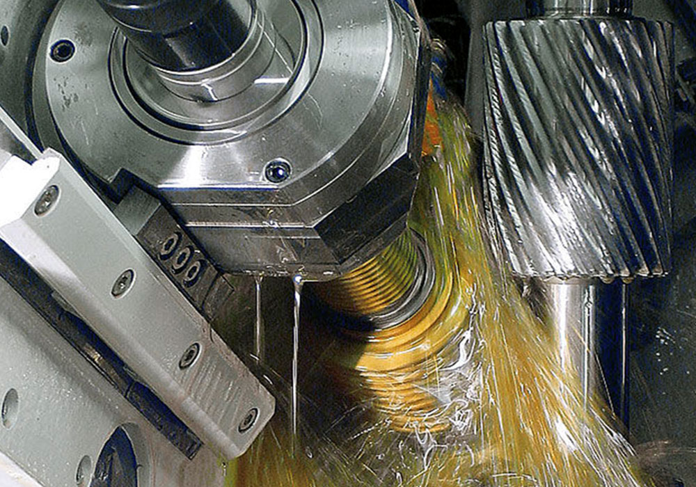
Optimising gear mesh is crucial for performance, involving precise tooth profiles, controlled backlash, and contact pattern analysis. CAD/CAM software aids in designing tooth profiles for smooth meshing, reducing friction and noise. Backlash, the space between mating teeth, must be balanced to avoid binding or vibration.
Engineers use CAD/CAM simulations to adjust contact patterns, ensuring even load distribution and gear longevity. Noise and vibration, often overlooked, are addressed by CAD/CAM tools to refine meshing conditions for quieter operation. Testing and iterative design, streamlined by CAD/CAM, validate gear functionality and allow rapid specification adjustments. Emphasising gear mesh optimisation with CAD/CAM tools leads to durable, reliable gear systems, preventing maintenance issues and failures. Neglecting these aspects can result in increased wear, poor performance, and costly downtime.
Gear design is an art form, deeply influenced by environmental factors like temperature and humidity, which can cause wear. CAD/CAM tools simulate these conditions, guiding the selection of materials and lubricants to enhance gear durability. Proper lubrication is crucial for reducing wear and friction, and CAD/CAM software helps optimise lubricant selection and coverage. Gears face dynamic loads and vibrations; CAD/CAM simulations improve design robustness and reliability. Dirt and dust can lead to wear, but CAD/CAM evaluations help in choosing effective countermeasures.
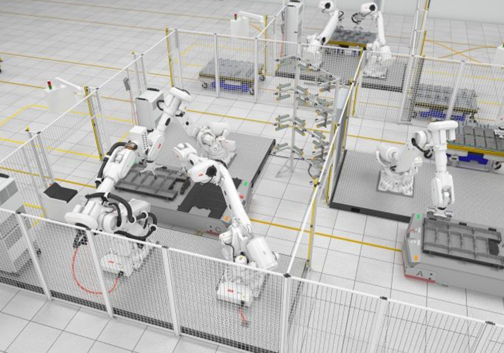
Gear performance varies with operational conditions; CAD/CAM analysis ensures gears perform consistently under different loads and speeds. Predictive maintenance, facilitated by CAD/CAM integration, allows for real-time monitoring, preventing costly failures. Engineers use these tools to create gears that are robust, efficient, and durable, ensuring optimal performance in their operational environment.
In the evolving gear industry, experienced designers leverage new materials like advanced composites and 3D-printed metals to enhance gear strength, efficiency, and weight. Innovative tooth designs, surface treatments, and specialised lubricants are combating friction, extending gear lifespan even in harsh conditions. With AI, simulation, and finite element analysis (FEA), CAD tools are evolving to design lighter, stronger, and more efficient gear systems. 3D printing has moved beyond prototyping, now used to craft intricate gear structures and unique gears for specific needs.
Noise reduction is also critical, with cutting-edge materials and production methods leading to remarkably quiet gears. Seasoned designers are integrating these advancements with their expertise to keep their gear designs at the forefront, driving the industry into the future.

We are India’s first and only multifaceted Web Platform catering to Indian Gear Manufacturers & Gear related Industries.
![]()