In recent times, gear hobbing machines have updated themselves with modern features like backlash free drives, high dynamic rigidity, auto tool changer, CNC controls, increased machine power, improved cutter materials and cutter coatings.
Therefore, it becomes imperative to consider all these features, so as to obtain least cost per piece.
The following guidelines attempt to systemize the modern knowledge of hobbing, and to assist gear process engineers in the selection and determination of various hobbing parameters for cutting gears efficiently.of course, it is not possible to consider all the variables influencing the hobbing operation.
There can be differences of opinions regarding the best methods to hob gears.
Nevertheless, these guidelines can effectively serve as a beginning for a various number of applications.
1. Selection of Number of Starts
This depends on the module, the number of teeth in a workpiece, the stage of manufacturing program, the required gear quality, and the divisibility of the number of starts with the number of teeth on the workpiece to be cut.
Generally, productivity increases when hobs with greater number of starts are used.
The following table refers to the multi-start hobbing limitations with respect to module and number of workpieces to be cut.

The table below also factors in additional limitations with respect to the DIN quality class desired.

2. Selection of Number of Gashes
As evident, the more the number of gashes there are, the more cutting edges are engaged in the cut which results in lower cutting loads and less wear.
The greater number of gashes increases the number of enveloping cuts which make the involute smoother. This is especially important when cutting gears with small numbers of teeth.

3. Selection of Hob Diameter
A small hob diameter usually results in less cutting time since a higher hob RPM is obtained. Furthermore, it cuts down the total hobbing traverse by decreasing the approach and overrun distances.
However, the limiting factors for reducing the hob diameters are usually the minimum number of gashes and the hob lead angle.
The maximum lead angles for the hobs with straight gashes are usually within 6 degrees.
The hob accuracy selection is based on the required DIN gear quality, stage of manufacturing, and number of starts.
Class AA hobs are recommended for finish hobbing of parts that require DIN 7 or 6. Class A hobs can be used for parts that will subsequently go for gear grinding.
1. Number of Cuts
The selection of the number of cuts is influenced by pitch, number of teeth in the workpiece, stage of manufacturing, surface finish, and gear quality.
A two-cut cycle can be selected for gears with a module greater than 3. For small numbers of teeth, less than 12 pitch, and a module greater than 3 is when a two-cut cycle should be used.

2. Cutting Speed
This is usually selected based on cutter material, coating as well as workpiece material, hardness and module. Similarly, hob speed is also usually selected based on cutter material, coating, workpiece material, hardness, and module. For coated hobs, the speeds can be increased to 10 ~ 15 %.
For gears above 3 mm module, the greater the module of the gear, the more the cutting speed is to be reduced. The above table reflects the guidelines and data to be used with caution.

3. Feed
NOTE:
There are numerous cycles that can be used. The selection of the hobbing cycle depends upon workpiece configuration, work holding fixture design, hob size, surface finish, and ultimately gear quality desired.
These hobbing cycles are mainly governed by the feed direction employed. They are classified as follows:
The cutting time for axial hobbing is calculated, for a one-cut cycle, is as follows:

Where:
T=Hobbing time; Z2=Number of teeth in the workpiece; Z1=Number of starts in the hob; n1=Hob rpm; Sz=Feed per work revolution; A=approach; b=face or width of stack of workpiece(s); O=Hob overrun
Hob approach travel is calculated, for spur gears, is as follows:

Where:
h2=whole depth of cut; dk1=hob diameter
For helical gears, the calculation is:
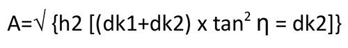
Where:
dk2=workpiece diameter; η=hob head swivel angle
Hob overrun is calculated as:

Where:
β = helix angle of the workpiece; α = normal pressure angle
There can be many other criteria that might arise to be considered like machine selection, sourcing of workpiece as presented to the hobbing machine, part inspection, material handling and movement. However, with the knowledge of the above guidelines, it will help the gear manufacturing engineer to plan the process very well in advance.
It will give an insight in the procurement of hob cutter, development of workholding fixture, adopting a suitable hobbing cycle and target the overall stages of gear production leading to desired quality and productivity.
This will also help estimate the hob tool cost per piece based on the procurement cost, sharpening and coating costs.
Further, based on the machine hour rate and productivity achieved, one can estimate the machining cost per piece, and in totality the overall cost per piece.
 Vishwajit Kothari, CEO, Cyber Gears. Former Head, Sales & Marketing, Premier Ltd. He has 32 years of experience and knowledge in machine tools, machining processes, tooling and workholding fixtures & application engineering.

We are India’s first and only multifaceted Web Platform catering to Indian Gear Manufacturers & Gear related Industries.
![]()