By: Mahendran Muthu
It’s interesting to note that after freezing the gear geometry and drawing release, most design engineers don’t seem to be particularly interested in verifying the quality of the gears during the various stages of manufacturing process on the shopfloor. There is an insufficiency of control data in drawings for setting the job, tools, fixtures, and quality inspection parameters that leads to non-conformities and deviations in many functional parameters of gears. There is a silent reduction of the torque transmission capacity without anyone noticing. Among such parameters is the transition from flank to root form which decides the transverse contact ratios for better root strength, smooth torque transmission, and avoids the interference with the tip of the mating gear teeth.
Undercut
For gears finished by grinding, the semi-finishing tool is usually designed with protuberance geometry that would generate an intentional undercut in the gear to prevent a grinding notch.
The protuberance provides stock for finishing operations like grinding. Here, the root circle is created by the pre-machining cutter and the flank and the final root form diameter is generated by the grinding process.
Form Diameters
The root form diameter (dFf) is the diameter of a circle at which the trochoid produced by the tooling intersects or joins the involute or specified profile. It is where the involute (unmodified or modified) part of the flank begins. It results from the respective final machining like grinding. It is a part property and not a gear pair property as is the case for the active root diameter (dNf).
The active (usable) root diameter (dNf) is determined by the starting or finishing point of the path of contact that is by the intersection of the usable tip circle of the mating gear with the line of action. The form diameter (dFf) of the finished gear must be smaller than the active root diameter (dNF) which is also called start of active profile (SAP) of the gear when the gear meshes with the mating gear.
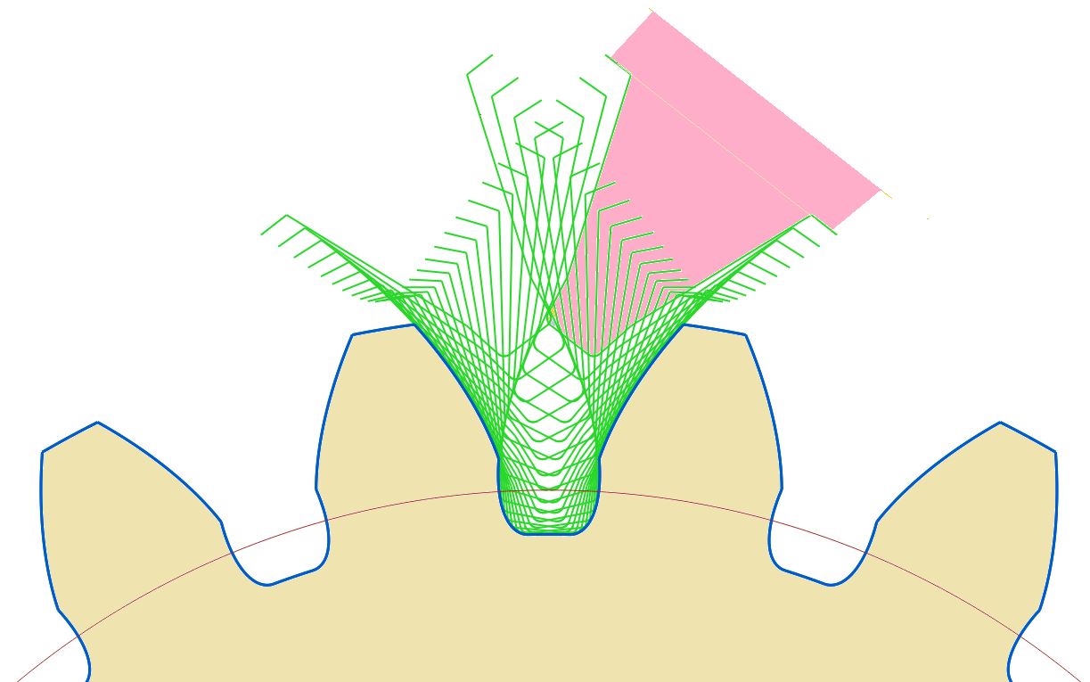
 Fig 1: Undercut formation during hobbing
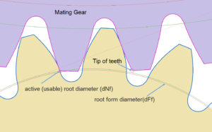 Fig 2: Root form diameters related with mating gear
Grinding Stock
It is important to maintain optimal stock during the hobbing process by considering the possible heat treatment distortions, root fillet / undercut proportions and required dNf or SAP parameters. If the undercut is insufficient, a grinding notch will form. If the undercut is higher, then the tooth root strength will be compromised. The process team then uses the state-of-the-art design and simulation tools (like KISSsoft) to ensure that the first time right tool (PGP Hobs) goes through excellent process control measures with validations. In many of the cases, the notches are not permitted to avoid stress concentration and tooth crack initiations.
To achieve the optimum gear tooth strength, the fillet portion has to blend as closely as possible nearer to the active root end of the involute profile. The shape of the transition zone is based on the protuberance height, protuberance angle, tip radius and the involute producing section of the hob cutter. The design computations must calculate and generate this condition with the grinding stock needed as per process engineering GD&T (Geometric Dimensioning and Tolerancing) parameters and heat treatment distortions.
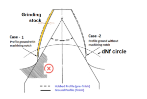 Fig 3: Grinding notch formation
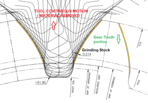 Fig 4: Simulation using tool geometry
Software Computations
In KISSsoft, it is a simple and user-friendly method to create tooth shapes using a Tooth Form-Manufacture Cylindrical gear with a gear generation process (Cutter, Grinding wheel) option. An in-built intelligent algorithm suggests the tool parameters based on pre-final and final process selection, and the designer can modify those measurements accordingly.

Fig 5: KISSsoft user interface Tooth Form – Manufacturing cylindrical gear with a gear generation
Sample Design
To explain the procedure, let’s take a sample design, module mn = 6mm pinion with 19 teeth, protuberance hob parameters are sized and simulated in KISSsoft software, by considering the grinding stock 0.263mm. While the geometry is frozen for design rating, export the gear geometry.dxf or .dwg file as the master reference to merge or overlap with the manufacturing simulations (example: design.dxf).
The first stage is to generate the gear geometry through the hobbing process in a manner that the hob depth (addendum, dedendum) is fixed, so that the generated root diameter is merged with design root diameter keeping the grinding stock for final machining. Next, fix the appropriate manufacturing shift coefficient (XE) value through the sizing option. A key point to take into account is the heat treatment distortions, and the operator requiring allowances during grinding machine job setting.
However, it is a simple task while using the sizing option in the software which is a one-step process. Run the generation process and export the manufactured gear geometry in .dxf or .dwg file (example: hobbed.dxf).

Fig 6: Protuberance hob parameters (sample for 6 module gears)
The second stage is generating the standard grinding process (in general the grinding wheel parameters are standard 1.12 times depth for tool addendum and dedendum as shown in fig.5 Kisssoft user interface). During this stage, the manufacturing shift coefficient (XE) value shall be default “Final Machining”. Run the generation process and export the manufactured gear geometry in .dxf or .dwg file (example: ground.dxf).
The tooth form can be visualized after each step of the above process, and the results of several steps can be placed on top of each other in order to show the material removal from one step to the next. The manufacturing process of tool and gear is also visualized in graphical form in the software itself or exported to other CAD systems in native / neutral formats. Merge all the three files ( design.dxf, hobbed.dxf, ground.dxf) in a 2D CAD software by placing them in different layers or different colors for easy identification of tooth root forms, whether a grinding notch is formed or not. The notch effect may induce 20 percent of power rating capacity reduction in gears while put into maximum operating load. By analyzing and predicting the “grinding notch”, the designer can re-validate the safety factor for bending accounting notch (ISO6336-3, factor Ysg or through FEM calculation integrated in KISSsoft), can also ensure that the manufacturing process in the factory is in control.
Summary
The gears after manufacturing (in each stage) shall be inspected for the compliance on root form diameters, through profile inspection in gear CMM to ensure the design validation and further continual improvements in tool design. The gear design engineer takes the responsibility of hand holding the project though quality inspections by aligning all stakeholders in manufacturing, heat treatment and quality control, so there’s no requirement to do multiple iterations. The need to say “quality is not at any additional cost” is not required if a focused attention and an innovative approach were in practice at every level. Therefore, it is worthy to focus on gear root forms to harness the optimum torque transmission.

We are India’s first and only multifaceted Web Platform catering to Indian Gear Manufacturers & Gear related Industries.
![]()