Small Dimensions with Huge Potential
Author Gear Technology India on June 19, 2023
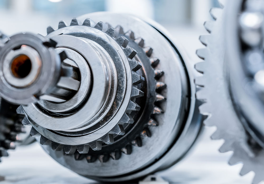
Generating grinding with dressable tools is very productive. Workpieces with interference contours, however, such as two gears on one shaft, impose limitations on conventional grinding worms. In order to avoid time intensive processes such as profile grinding with small tools or honing, the tools have to be configured to be very small. This is possible by optimizing the worm, tooling and technology accordingly to fit the workpiece and machine.
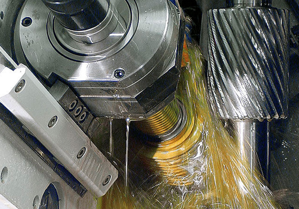
Generating grinding with dressable tools is a common process for series production. Despite the auxiliary times for dressing, the advantages prevail: cutting speeds between 63 and 80 m/s provide high productivity. This is accomplished with conventional tools such as grinding worms with a diameter of 300 mm and approximately 5,000-7,500 RPM.
The large tool diameter, however, causes problems with interference contours because the tool requires room next to the gear to finish its grinding path. Typical examples are a bearing seat or an adjacent gear near the gear to be processed. It is possible to utilize tools with smaller diameter, but unless the RPM is increased, the result would be lower cutting speeds.
Furthermore, standard machines are generally not capable of accepting small tools or processing workpieces with such small center distances without encountering interference conditions. Conventional generating grinding machines require a minimum tool diameter of at least 170-200 mm. This is why manufacturers had to resort to other, less efficient processes for critical workpieces.
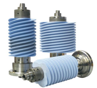
Small generating worms
Conventional processing of interference contours
The traditional process for hard finishing of gears with interference contours has been discontinuous profile grinding or gear honing. Both processes are suitable for complex components; however, they are not as productive and economical as continuous generating grinding. The outside diameter of dressable and non-dressable profile grinding wheels can easily be reduced to 30-50 mm with CBN plated wheels. They also do not require as much axial clearance next to the gear being processed compared to a grinding worm. However, this process does involve long auxiliary times.
Another alternative is gear honing which is a process during which the profile of the honing ring meshes with the workpiece and removes material. Due to process-related reasons, however, the cutting speed of honing is very low which in turn demands higher operating forces. This process is therefore not suitable for gears with large moduls or large gear widths as the forces during processing would negatively influence quality, cost and productivity.
Despite these disadvantages manufacturers had to resort to either of these processes even for large series manufacturing. Continuous generating grinding of interference contours had not been an option due to the lacking capabilities of gear grinding machines. The dynamic demands to tool and workpiece drives, in particular, were too high. Meanwhile, new market developments have closed the gap.
Continuous generating grinding with small tools
Kapp Niles developed the gear centers KX 160 TWIN and KX 260 TWIN specifically for hard finishing of gears with interference contours using the continuous generating grinding process. Thanks to high speed grinding spindles these machines are now capable of generating grinding gears that require a tool diameter as small as 55 mm.
In combination with a maximum possible tool width of 180 mm this allows for processing times and costs that have so far not been possible for gears with interference contours while at the same time meeting the quality demands common to series production.
Thomas Nitzsche, project manager for small grinding worms at Kapp Niles, explains, “A typical tool drive has max. 7,500 RPM. In order to reach the same cutting speed with a small tool, a RPM of up to 25,000 is necessary, depending on the tool diameter. This creates completely different forces than commonly expected on traditional machines: the workpiece must rotate faster proportional to the tool RPM.
Kapp Niles specifically considered this and provided the standard workpiece spindle with 5,000 RPM.” Aside from the high forces, restricted space also posed a unique challenge for the developers: each tool required a stable, quick-change mounting, and the tool arbor had to accommodate the entire sensor and dynamic technology: the machine detects contact between workpiece and grinding tool, or grinding tool and dressing tool respectively, via structure-borne noise sensors. Automatic balancing of the tool arbor on the machine is integrated into the arbor itself, as well.
Shorter auxiliary times thanks to second workpiece spindle
In order to increase productivity yet more, the machine concept includes two identical workpiece spindles, which are positioned on the indexing table opposite each other. While one workpiece is processed on one spindle, another workpiece is automatically unloaded and loaded on the other workpiece spindle and then aligned.
This reduces the auxiliary times to a minimum. The machines are suitable for external, spur and helical gears. Optimal measuring systems determine profile and flank, runout and gear width.
Thomas Nitzsche continues, “With these two gear centers, we are targeting high production volumes of large and series manufacturing for gears of high-quality requirements. It was therefore important for us to explore all possible options to maximize productivity. Obviously, in addition to the small diameter tools, these machines can handle larger tools with diameters of up to 200 mm, as well. As such, they are quite suitable and not to mention economical for processing of workpieces without interference contours.”
These small generating grinding worms have definite advantages over profile grinding with CBN wheels. The following comparison demonstrates this clearly.
Small generating grinding worms in direct comparison
Dr. Sergiy Grinko, a key contributor to this technology development at Kapp Niles, presents two typical cases:
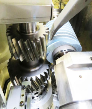
Image SEQ Abbildung \* ARABIC 1: Generating grinding of a gear with interference contour
“If two gears are positioned on one axis with little distance between them, there is insufficient room for a generating worm. That means, one would have to use profile grinding or small ceramic worms.” Image 1 demonstrates such application.
Sergiy Grinko calculated the cycle time for one specific customer workpiece. The result: non-dressable profile grinding with a CBN wheel required a cycle time of 5.4 minutes versus 2.9 minutes for dressable generating grinding with a dressing interval of 25 workpieces.
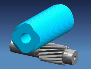
An additional example shows a gear with runout in the bearing seat (image 2).
Image SEQ Abbildung \* ARABIC 2: Example of a gear with a hob breakout
Dr. Grinko explains, “A normal gear has a root diameter larger than the diameter of the bearing seat. In some cases this reverses and the runout may happen in the bearing seat.
A worm with conventional diameter can therefore not be used. And even in this case does the small grinding worm offer time savings: The example demonstrated that the processing with non-dressable CBN profile grinding wheels had a cycle time of 1.8 minutes versus 1.2 minutes with dressable generating grinding. The dressing interval reached 74 workpieces. Properly utilized, the smaller tools result in a clear productivity increase and present more than just an alternative to discontinuous profile grinding and gear honing.”
The author, Martin Witzsch, is a freelance journalist for
Kapp Niles (www.witzsch.com)
Post Views: 97