It is important to evaluate a number of parameters using Fractal Geometry in gear design/life. Here’s how it’s done
Quite often gear tooth finish machined surfaces when in motion under load experience abrasion wear. The unavoidable abrasion wear is controlled or managed by lubrication where the mineral oil as the lubricant acts as a pressure sustaining medium to separate the load bearing surfaces. Here, the lubricant’s EHD (Elasto Hydro Dynamic) or full film characteristics retard the flank surfaces to undergo abrasion wear. The transition from EHL (Elasto Hydro Dynamic Lubrication) towards mixed lubrication has several phenomena.
As the predictable gear life from surface finish to micropitting gains importance in gear design it is necessary to evaluate the loading pattern, elastic tooth deflection, transition zone between EHD and mixed lubrication, and asperities behaviour systematically.
It is a complex topic to go into the details of every aspect in one coverage. The contemporary research efforts address the wear growth rate and micropitting features under different factors. Accordingly the surface feature analysis using fractal geometry achieves an attention for convenience in mathematical interpretation and addresses the physical characters through fractal dimension.
Fractal Geometry: Using Fractal Theory To Determine 3D Phenomena
Fractal Theory is used to simulate rough surfaces with fractal characteristics. The rough surface profile is shown below in
figure 1:

This surface has the 2D roughness profile and considering the face width along with profile contact enables one to observe a 3D phenomenon of rough surface topography. The associated features are:
Z represents contour height in 2D rough profile, x a position coordinate, D the fractal dimension, G the scale coefficient, γⁿ represents frequency spectrum of surface roughness where γ takes a value of 1.5 or less, and n being the frequency index of asperities.

The above concept and height of 2D rough profile cannot characterise the fractal property of 3D rough surface or for gear tooth surface in mesh contact of tooth flanks except X direction to indicate the rolling direction. As the actual tooth surface has the morphology which is anisotropic the 3D WM (Weierstrass & Mandalbrot function) of anisotrophy can be obtained by superimposing 2D WM function with X and Y directions. Therefore the previous equation (figure 2) becomes as seen below in figure 3:
![]()
where Z(x, y) is the amplitude of 3D rough surface. Dx & Dy are the fractal dimensions along the X and Y axes respectively. Gx & Gy are the scale coefficients for X and Y directions. φnx and φny are random phase conditions while other parameters remain the same.

The 3D surface shown in figure 4(a) and 4(b) gets merged into a shape as seen in figure 4(c).
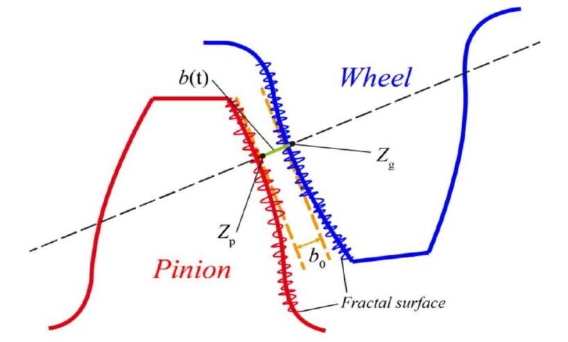
The sketch of the pinion and gear wheel fractal surface for 2D surface topography can be realized as shown below:

Fractal Tooth Surface:
The surface wear evaluation by prediction method for tooth surfaces is subject to a complex contour and requires integration of a few separate models after analysing the microgeometry features. These can be described as follows:
The prediction of abrasion or material wear of tooth surfaces will evolve microgeometry features and associates with contact stresses between the flanks and the load. It also includes implicitly the effects of sliding between meshing tooth surfaces. The amount of sliding can change with slip per design.
Slip S = Ur / Ue.
Ur = Surface velocity of rough surface.
Ue = Mean entrainment speed.
The models that come are:
For the construction of real tooth surface models of a gear pair there is a need to segment the active phases theoretically to explain the microgeometry. It is done better using a CMM (Coordinate Measuring Machine) where the measured coordinates of a tooth surface can be converted into a 3D curved surface analysis. The use of projections to get nominal points in spatial domain under aerial metrology with surface normals and unit vectors yield the expected point coordinates.
b) Load distribution model is to measure the contact pressure at each point of mesh along with the angle of rotation in every mesh cycle.
Modified fractal method is used to estimate the deformation since the manufacturing process of involute gears may be irregular due to several reasons yet the tooth flanks have fine structure and statistically compatible. Hence WM function is applied to describe the micro geometrical features to relate the operating conditions to wear and its progression.
![]()
ζ is the profile parameter of asperity, is the fractal roughness of actual tooth surface, D is Housdorff-Besicovitvh fractal dimension, δ is the frequency factor, and γ a scaling parameter: γ is chosen between 1 and 2, and 1.2 often applied.
When D and γ with properly chosen values gives W(ζ) in the above equation, seen in figure 6, a deterministic value. The elastic deformation of an asperity of real tooth under meshing condition is represented as seen below in figure 7:

Then the normal elastic contact load is finally arrived at after finding the elastic contact area, modified contact radius of curvature of asperity as:
![]()

The cross-sectional tooth contact load bearing profile normal section is shown in figure 9.
Full plastic contact load on the asperity is found by calculating the plastic area of contact ap: fixing δc the critical deformation between elastic and plastic range of asperity and finding whether δc < δe and if so the deformation of real tooth surface model is a full plastic deformation regime.


H represents the actual gear tooth surface hardness.
Sliding distance, local contact pressure, and direction of wear progression are key factors for abrasion wear growth. Following Archard’s method for local contact point can be represented as seen in figure 12:

Where S1 is a sliding distance of a contact point on pinion and gear real tooth surfaces. K is the wear coefficient.

The wear depth h of any contact point can be calculated by the above expression.
Conclusion
Gear tooth wear mechanism and wear progression under operating factors such as those which chiefly influence in
consideration have been adopted to model the phenomena. The wear contributing factors have different impact on the wear value, rate of progression and direction towards ultimate micropitting.
The fractal features such as D, G, γ, n or δ while transforming into analytical way enable a useful correlation of actual factors on the real tooth surface wear without changing the logical impact.
Taking specific criterion like the work done on the asperities under elastic deflection of real tooth surface the equation under the load distribution model shows that it is a function proportional to actual surface fractal roughness raised to a power of fractal parameter D. In practice the real value and its rate affecting the gear surface finish worsens in proportion to the load continually. Similarly, area of deformation under force is also proportional to the load expressed as exponential function of the fractal parameter D.
What Lies Ahead: Scope and Direction of Future Efforts
The introduction of fractal characteristics of their parameters is applied to other areas as well. Determination and monitoring wear on grinding abrasive worm used in generating grinding of gears is an important phenomenon to capture for it helps to:
a) know the grinding wheel behaviour on the load
b) suitability of grinding wheel specification for the given
application and scope to improve
c) monitor the dressing interval in process
d) impact on the quality of the gear in grinding and so on
The process software has the method existing already to decide the dressing frequency, the grinding wheel surface quality in dressing, depth and mode of dressing. Yet the area may need more research and automated applications than now in the
future.
Fractal features are finding their way in evaluating this approach using power spectrum method and applying WM
function on the effects of grinding volume Vh and thereafter the specific material removal rate Qw’, axial feed rate, tangential grinding wheel shift, shift increments, and number of starts of grinding abrasive worm under closed study in research domain. The influence of lubricating oil film pressure and its effect on wear deceleration may also be considered in gear tooth surface wear prediction probably in the future.
The growth of artificial intelligence for application into process management, determination of gear tooth life and specific design loads and stress cycles with consequent failure analysis to seamlessly integrate at the design stage itself for performance prediction may be expected in the gear industry in the future.
References:
 The author is former Director and

We are India’s first and only multifaceted Web Platform catering to Indian Gear Manufacturers & Gear related Industries.
![]()