In high-speed gearing, one of the known independent power losses is windage. This is an important area of losses although gearing efficiencies reach 99% in a well-designed gearbox. Windage is rather complicated and less understood fully due to 1) aerodynamic drag forces 2) function of the variety of parameters like shape, size, rotary speed, lubricating oil density, viscosity, 3) operating conditions in rotational resistances, and local heating, and 4) multi-face fluid flows.
Gears connected to gas turbine engines, reduction ratios as well as fluid mixture behavior can offer complex situations to measure and correct optimally.
In dealing with calculations involved in estimations of windage, the gear dimensions, weight, speed, shape and many gearing related geometry as well as simplicity of understanding the flow around a rotating body helps to derive a frictional moment M in a laminar flow which can be expressed as:
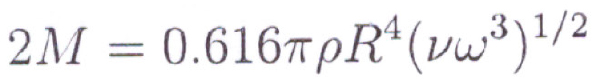
Fig 1
based on Schlichtang’s functional resistance of an ideal disk considered in place of a gear.
When the laminar flow gets into the turbulent flow the same 2M [[Image Pg 14 of Computational Investigation of Gear Windage equation 1.6] as the viscous torque where:
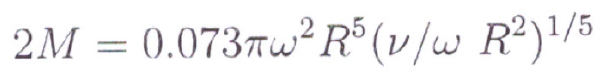
Fig 2
ρ is the density, R is the radius, V is the Kinematic Viscosity, ω (omega) is the angular viscosity.
These provide a simplest solution only; the effect of the rotating part becoming a gear – its shape, the orientation of diameter/face width, helix angle, and the number of teeth add to the complex solutions.
The flow physics inside a gearbox are quite complex. Gears are not designed to be aerodynamically efficient. The shape and profile of the gear teeth has an important function in transferring power between gears.
Variations in angular velocity of the driven gear will lead to vibrations in the train and will generally cause fatigue cracks to form in the teeth resulting in early failure of the gear.
The teeth are located at the periphery of the gears where speeds are greatest (speed = ω x r). It is very possible that depending on the rotation rate and size of the gear, the gear tip speeds can enter the range of compressible flow.
Compressible flow effects typically become noticeable above Mach number of 0.3.
However, sonic speed is effective by both the temperature and the composition of (air-only versus air-oil) of the fluid environment.
In 2005, Brennen showed the solid velocity of a homogeneous mixture (air and only) can be much smaller than that of either of its constituents, meaning that compressibility affects could be a concern at lower speeds than an air-only analysis might indicate.
We see a few of those areas where research in this field has contributed to a better level of understanding.
Anderson & Lowenthal who researched in turbine class and aerospace applications – considering fluid flow around the gears determine the windage loss:
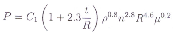
Fig 3
Where C1 is a constant; t is the face width of the gear; R is the pitch radius; n is the speed, ρ and μ are respectively the density and viscosity (centipoise) of the fluid medium surrounding the running gears.
They accounted air and oil to a ratio of 34.25 to one part of oil combination of the lubricating oil to correct the density/viscosity and change their formula to:
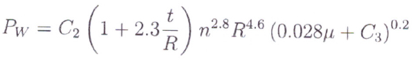
Fig 4
But even here they did not consider helix angle and module as factors since they use spur gears only usually in cylindrical reduction in helicopter gears.
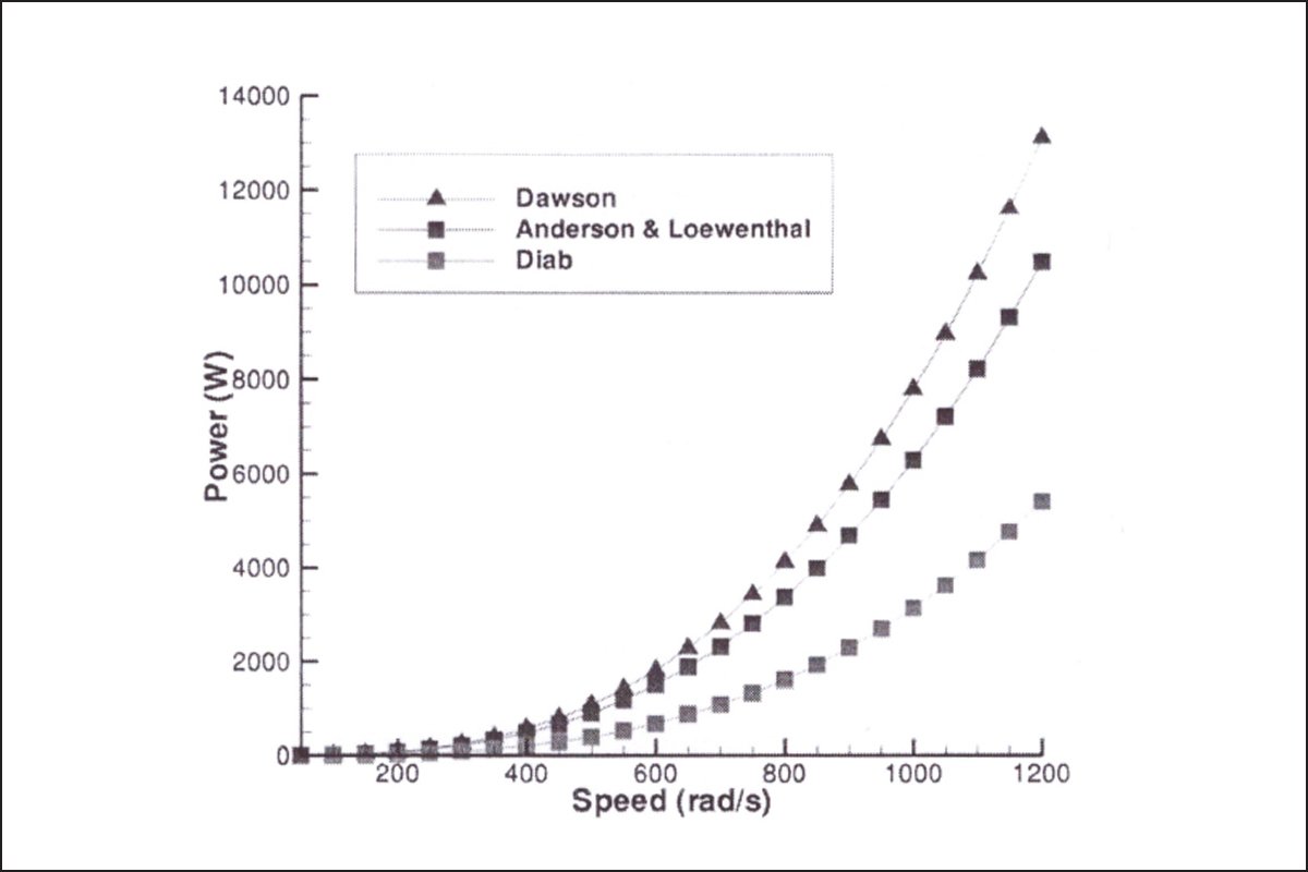
Dawson developed his own method – well known in windage loss estimates, and often applied by gear design softwares as a function of speed, root diameter D, face width F, module M and without helix applied as:
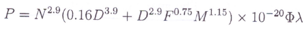
Fig 6
Where C represents the shape of the gear, just as an example, as a large diameter, longer face width, and smaller module, more number of teeth scenario.
Such gears are common in high-speed turbine gear where the windage loss is very critical for accounting the power loss. There is a point mentioned here that even in estimating power loss factors – one of the methods identified as Niemann’s method reference of factor K on the line of action as a location from the pitch point is found well-placed in Niemman’s method.
For such type of FRICTION LOSS APPLICATIONS in high speed Gear , my understanding is KISSsoft software must be referring to this method.
Well known Diab method estimates even more closely using a factor CT in evaluating windage loss in watts.
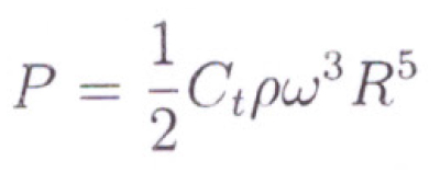
Fig 7
Where he finds Ct as a function of:
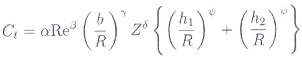
Fig 8
R,Z,and B are pitch radius, number of teeth, face width respectively and α, β, γ, δ and Ψ are constant coefficients derived by experimentation with chosen fluid medium, and Re being the Reynold’s number, h1 and h2 represent a condition whether any flange is present near the teeth.
When no obstacle to the flow of the medium, h1; h2 = 0.5 ^1/ Ψ R. Another detail is a method that uses a split in Ct to fix Cb and Cl.
This explains the physics behind the contribution of face width, and gear tooth module divided into height-wise X profile shift coefficient and along the involute the pressure angle set at pitch point under the tip of the pinion/gear in conjunction with fluid flow under laminal flows.
The subdivisions mentioned here is a critical Reynold’s number Re* the form of which can be used a limiting value of 3×10^5 as a reference.
This is to identify the change from laminal flow to turbulent flow.
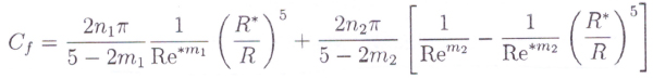
Fig 9
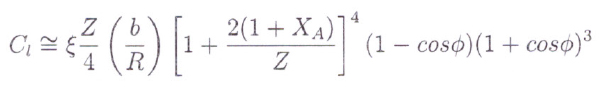
Fig 10
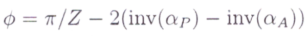
Fig 11
Where R* is the critical radius of pinion or gear that separates the laminar and turbulent regions. The tooth contribution coefficient is described in fig 10.
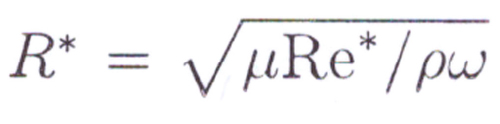
Fig 12
Hence, knowing this value the step to find Cl is shown above.
X is the profile shift coefficient and φ is a parameter representing the arc of involute from the pitch diameter to the tip diameter using the pressure angle.
The analysis considers that the fluid is expelled from the active tooth zone and pressure is uniform. (When pressure is changing with the temperature of the fluid, the flow gets into a more complicated zone, and the study goes more towards the effects of any heat transfer and geometry correction on tooth lead).
This change in pressure and temperature under fluid velocity in the teeth gap in the mesh zone and at ends after release from control volume shares the heat generated into the tooth flanks causing a change in temperature to modify the tooth correction.
That may involve Eckert and Prandtl non-dimensional numbers in use to solve partial non- linear differential equations/ Napier Stokes to infer the correction. That bifurcates the method in the route of lead correction topologically.
In multi-phase or in gears under an environment of oil/air – other than simple homogeneous difference.
Yet in the Eulerian approach each phase is treated as a continuum but different velocity/temperature when issuing out of control volume in a mesh environment.
Here the treatment includes mass transfer rate, drag force, non-drag force as one has to encounter different volume fraction, velocity/viscosity.
It can be seen to an extent solid particles/air in place of liquid/air in an explanatory discussion on fine particles/air flow in jet turbine engines for analysis of compressor blade tips getting impact by this very fine particle in aero-engine performance by Professor Tabakoff of the University of Texas using r, θ as polar co-ordinates.
It is a different topic of investigation of impact of solid particles on the tip of the rotor blades inside the turbine engine.
The physical mechanisms contributing to windage loss is the pressure field associated with the diversion and impingement of high-speed fluid flow of the leading tooth surface.
In high-speed gearing applications lubricant is applied to the gears by an oil jet system.
As oil jet is sprayed, it builds up then film thickness on the teeth, which is to machine friction.
Immediately after meshing the gear teeth that are sprayed again enable dissipate the heat (at least partially) generated during meshing.
The process of windage loss evaluation was worked by many researchers and some of the well known models have been shown.
A Computational Investigation of Gear Windage- Matthew J.Hill and Robert F. Kunz of Pennsylvania State University, Philadelphia,/Dec 2012

The author is former Director and General Manager of Gleason Works India. He has four decades of experience in the gear industry, with special reference to machine tools and gear processes. He is also a Fellow of the Institution of Mechanical Engineers, UK, and a registered chartered engineer.

We are India’s first and only multifaceted Web Platform catering to Indian Gear Manufacturers & Gear related Industries.
![]()